A while ago, I came across this strange thing called ‘split-ring compound epicyclic/planetary gearboxes’. They seemed really nice, extremely high gear ratios in compact, stackable modules. But the already existing models were not enough. I wanted to be able to design my own, and due to the lack of information on the subject, I had to do a little research and some math. Here is most of what I would have liked to find on the first place:
1. What is a planetary gearbox?
Planetary gearboxes, as their name says, resemble planets orbiting around a “sun”. They are composed of a sun gear, in the center, two or more planet gears around it -and often fitted to a carrier- and a ring/annulus gear on the outside. As an image is worth a thousand words:

Their main feature is a high reduction ratio in a small, flat space, and also, it is easy to couple the output of one gearbox to the input of another one, getting a two or more stage gearbox with such a high reduction ratio.
But where is the input and where is the output? In normal circumstances, either the ring, the carrier, or the sun gear is fixed, then, one of the remaining acts as input, and the other as the output.
2. Restrictions in planetary gearboxes:
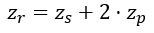
Where zr is the teeth of the ring gear, zs the teeth of the sun and zp is the teeth of each planet. This ensures that the space between the centres of the gears are correct for them to mesh properly. The third one only applies if you want the planets to be evenly spaced (which is recommended if you don’t want to mesh with counterweights to stop vibrations), and all the teeth in the same phase: zs and zr must be evenly divisible by the number of planets. If the teeth can be in a different phase, zs + zr must be evenly divisible by the number of planets.
3.Figuring out the gear ratio in planetary gearboxes:
The following formulas allow you to easily do that. Both are equivalent:
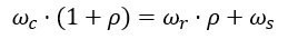
Where wc , wr , ws are the rotational speeds of the carrier, ring and sun respectively and p is zr / zs.
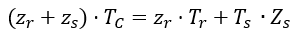
Where Tc is the turns of the carrier, Tr is the turns of the ring and Ts is the turns of the sun. Both of them work in the same manner, set the turns/ speed (does not matter, as long as you keep everything in the same units) of the fixed gear to 0, get rid of that term and rearrange.
4. What are split-ring compound planetary/epicyclic gearboxes?
As their name states, they have two different rings, one of them fixed. They also have compound planets, and two suns. Again, it is better understood with a picture.
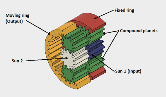
Souce: Myself
Sun 1 acts as the input, and the moving ring as the output. The compound planets are the key part: They are composed of two gears that share the same axis of rotation, but often with different number of teeth and module. Sun 2 just presses compound planets towards the moving ring. The gearbox could work without sun 2, but it would not be capable of handling much torque. So how do they work? The “first stage” (Sun 1 and fixed ring) make compound planets turn around the central axis of the gearbox, and that causes the output ring to also turn. But at the same time, compound planets rotate around themselves, moving the output gear in the opposite direction. As a result, the final gear ratio is the turns of the planets around the central axis minus the amount of turns of the output ring in the opposite direction that the planets rotating around themselves cause. It might seem complicated, but once
understood it is not.
5. How do I calculate their gear ratio?
Now it gets somehow complicated, but don’t worry, I have already done some of the work for you. The following formulae are a rework of the ones used above, but for this special kind of gearbox. The notation is the same as the one uses above.


Note from the future: Go read up on the Willis equation if you find these gearboxes of interest, much more general than this!
The derivation for w_r2 shown below is applicable only to this specific kind of planetary gearboxes, as is the code linked below.
But how I design the gearbox with the dimensions and gear ratio that I want? It is close to impossible to do that by hand, so I made a small python program that lets you enter this parameters and it will generate some possible so you can choose the one that fits your needs. It is not by any means a professional program and it won’t output every valid combination, but for most basic applications it should work. You can download it here.
This machine has one of these gearset inside of it: https://www.dasic-group.com/dasic-tank-clean/orbitor-100/ Water is pumped in the top and turns the sun gear, which causes the bottom part of the machine to slowly rotate.
ReplyDelete