
I will attempt to go over the general progress of the project, but please refer to the said thread for more information.
Design requirements:
- Dual isolated channels.
- Adjustable voltage and current 30 V , 500 mA per channel.
- Digital voltage and current displays.
Build stages:
First, the case was made out of a wooden board and 3d printed front and back panels. Heatsinks were taken from old computers. One side of a 2x 10Vac and a 15 Vac transformer power each channel, plus a 12 Vac smaller transformer for the displays, fan and microcontroller. Ac voltages are rectified and filtered on a separate board.
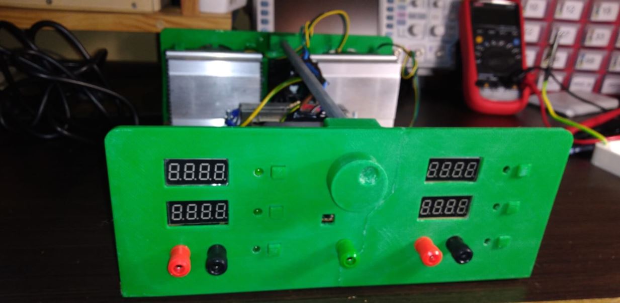

Here are some photos of the early development, initial circuit was based on the one found here.

Then came perfboard prototypes, testing and throubleshooting:


PCBs were designed using Eagle. This is my first computer-designed PCB, and it has been an interesting process going through several versions and then getting them manufactured.


Front panel overlay was designed on Inkscape, printed on photographic paper, and glued on:

User interface:
It is simple enough: each channel has three push buttons, set V, set I, and ON/OFF. Pressing one of the set buttons lights the appropriate led up and lets the user adjust the value by means of the knob. When the leds are lit, the display shows the set value, when they are not, the measured one. After a couple of seconds of inactivity, leds switch off. Voltage is shown in volts, current in mA.
The led next to the ON/OFF switch does what it is supposed to do. When in CC mode, all decimal points on the current display are on.
There is a "menu" key under the knob. At the moment, pressing it shows temperature and output power on the displays.
Firmware:
The firmware has several main tasks:
- Interface with the analog circuitry:
- Handle PWM to generate analog voltages that set voltage out and current limit.
- Measure output voltage and current.
- Detect CC mode.
- Measure temperature, and drive the fan accordingly.
- Calibration constants are hard-coded and should be adjusted before using the unit. I may write a calibration procedure that does this automatically and stores values on EEPROM.
- Handle user interface:
- Displays are driven using the required library, and data is given the appropriate format.
- Keys are read and leds are driven. Note that a single pin handles a button and a led, so keys are sampled periodically, making the pin and input and then back to an output. See schematics.
- Encoder is read by using interrupts.
- Handle serial communication:
- This power supply has two isolated channels, that communicate via opto-isolated serial.
- Channel 2 is the master and channel 1 is the slave. This means that channel 2 handles the encoder and the "menu" key, and it gets asked for its position by channel 1. Serial commands begin by '<' and end by '>'. Channel 2 also tells channel 1 to show temperature and power when the "menu" key is pressed.
- Handle error conditions: Shows an error code on the displays for the following conditions:
- E1: measured current greater than set current.
- E2: measured voltage greater than programmed voltage.
- E3: max temperature exceeded.
- E4: min temperature exceeded, that is, the thermistor is not connected.
So that is a brief summary. For more details, please refer to the mentioned EEVBlog thread. Again, all design files are available in this GitHub repository.
Comments
Post a Comment