.
Trying to fix the ballast tank isues, I attempted a 'surgery'.
A hole in the ballast tank was made to put some bulkheads in, see the photos:
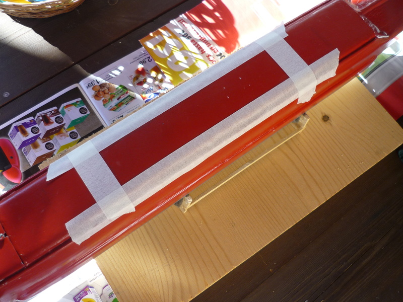
Hole shape marked. Had to go through 6-8 layers of paint to reach the metal!
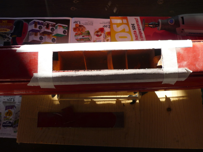
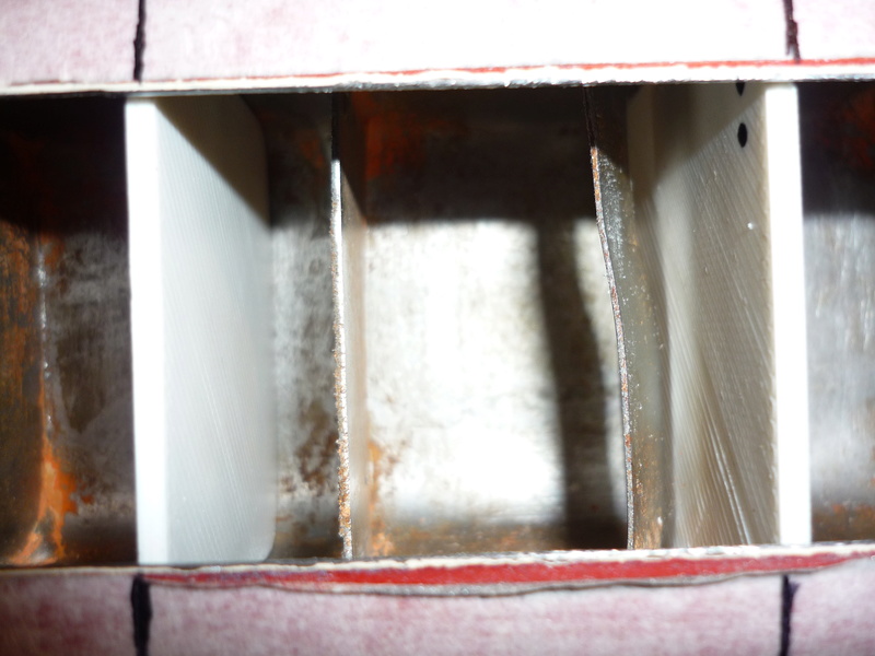
After cutting it. Notice the existing bafles, wich were there to prevent the tank from deforming under presure, but do not prevent water to move around.
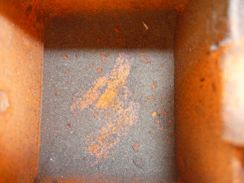
The inside, closer. You can see steel powder from the cut.
Everything was painted with minium /red lead paint. Had been 2 years closed, not smelling good. Paint was removed using a metal brush, with a mask as I don´t think swallowing minium powder is good for health.
Paint almost completely removed and 3d printed bulkheads trimed to fit:
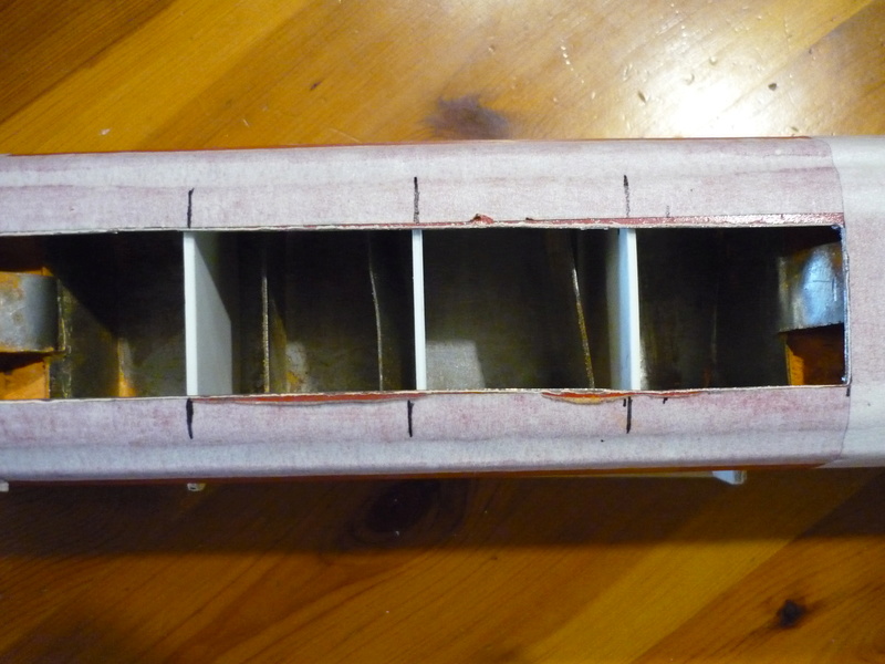
Now we have four independent compartments.
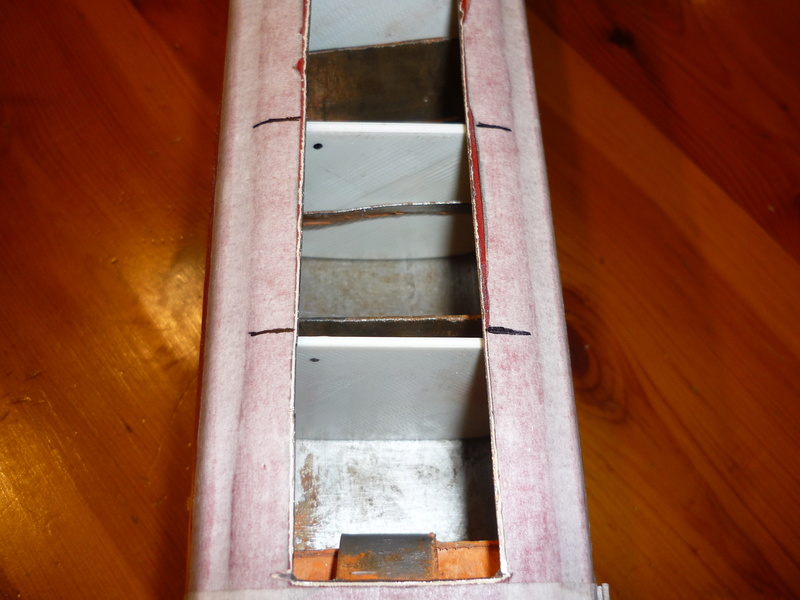
The bulkheads will be epoxy glued to the inside of the tank, and then everything will be painted.
Hole will be closed gluing another steel sheet to the underside of the tank. I am not really sure if epoxy will cope well with 4 atm, but I prefer that to welding, as I don't want to heat everything up. Lets see how it goes.
Trying to fix the ballast tank isues, I attempted a 'surgery'.
A hole in the ballast tank was made to put some bulkheads in, see the photos:
Hole shape marked. Had to go through 6-8 layers of paint to reach the metal!
After cutting it. Notice the existing bafles, wich were there to prevent the tank from deforming under presure, but do not prevent water to move around.
The inside, closer. You can see steel powder from the cut.
Everything was painted with minium /red lead paint. Had been 2 years closed, not smelling good. Paint was removed using a metal brush, with a mask as I don´t think swallowing minium powder is good for health.
Paint almost completely removed and 3d printed bulkheads trimed to fit:
Now we have four independent compartments.
The bulkheads will be epoxy glued to the inside of the tank, and then everything will be painted.
Hole will be closed gluing another steel sheet to the underside of the tank. I am not really sure if epoxy will cope well with 4 atm, but I prefer that to welding, as I don't want to heat everything up. Lets see how it goes.
Comments
Post a Comment