I am going to describe a project that I started in 2015 and needs some modifications to be done for it to work properly. I would be proud to hear sugestions!
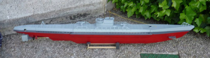
This is a radio-controlled model submarine. It is 1.06 m long and it is based on the german U-boots operational during WWII.
The main objectives were:
-Low cost : For now it is below 240 € without radio equipment (+- 150 €)
-Simple hull, made out of wood (later discovered that this was not the best material for underwater stuff!)
-Static diving
-At least one hour of battery.
-Operating foward dive planes and twin ruders (only four chanels, so no rear planes).
-Similar to an Type IXB german U Boot.
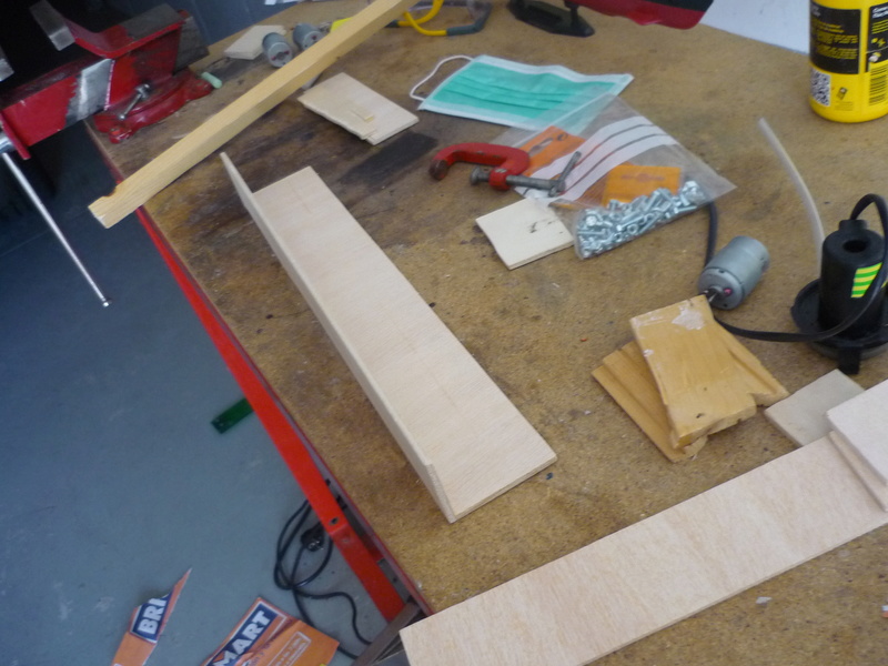
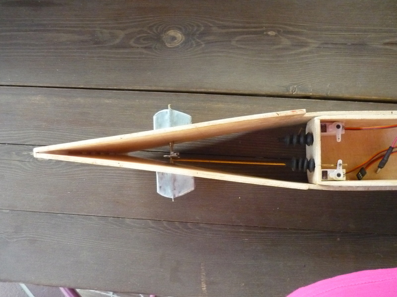
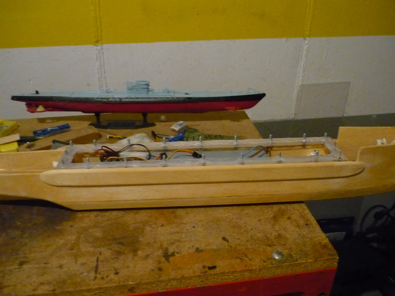
First stages from the build, as you can see, simple , square-shaped hull:
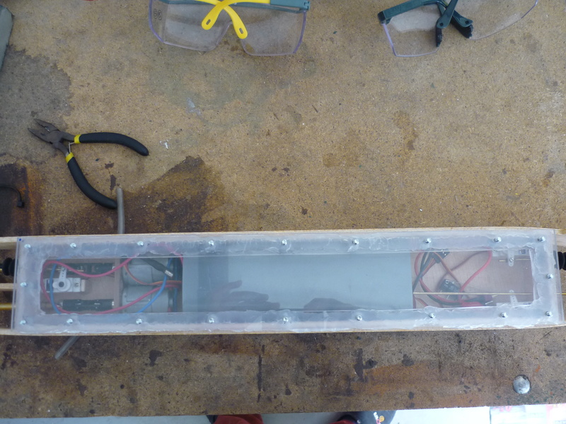
Water tight compartment.
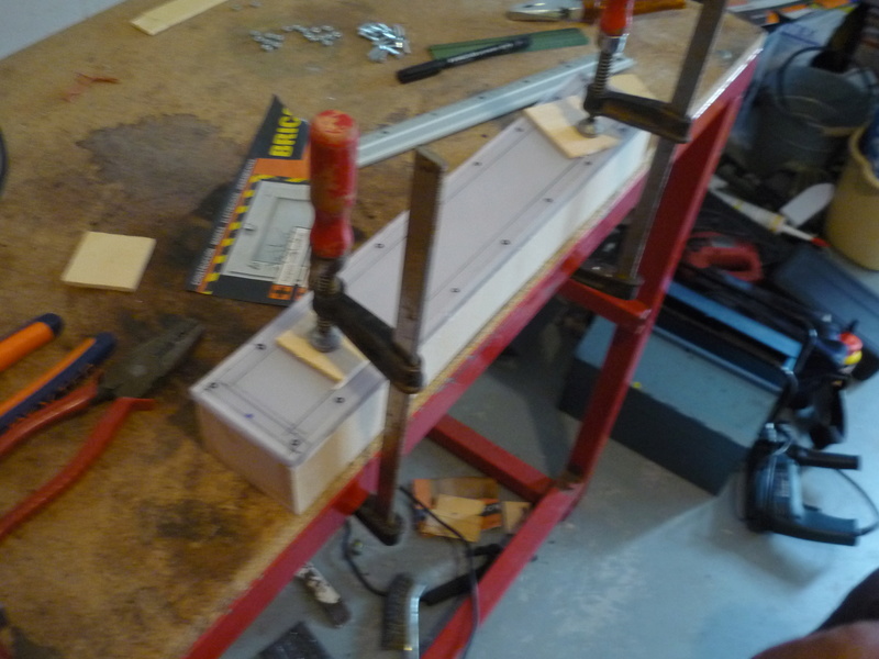
Policarbonate sheet cut and drilled to form the acess hatch.
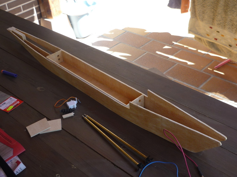
Hull construction, simple shapes, cheap and "easy".
Fore.
Aft.
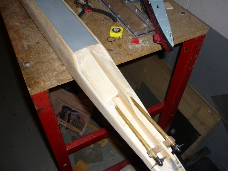
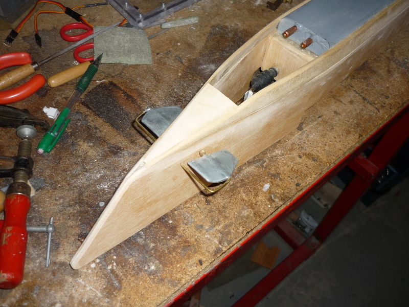
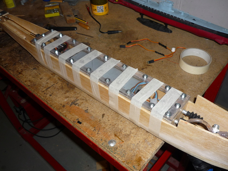
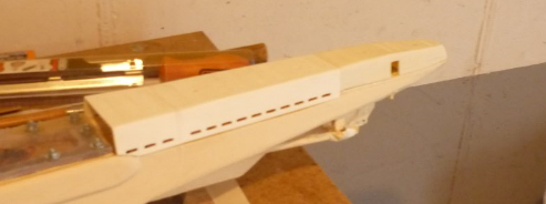
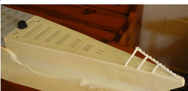
After foward and rear planes had been fitted, rudder assembly done, and frther hull work it looked like this:
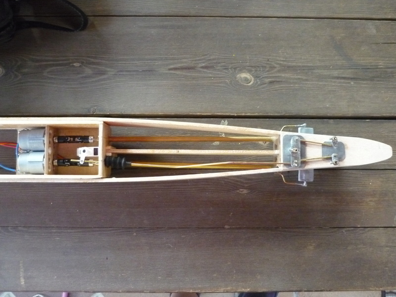
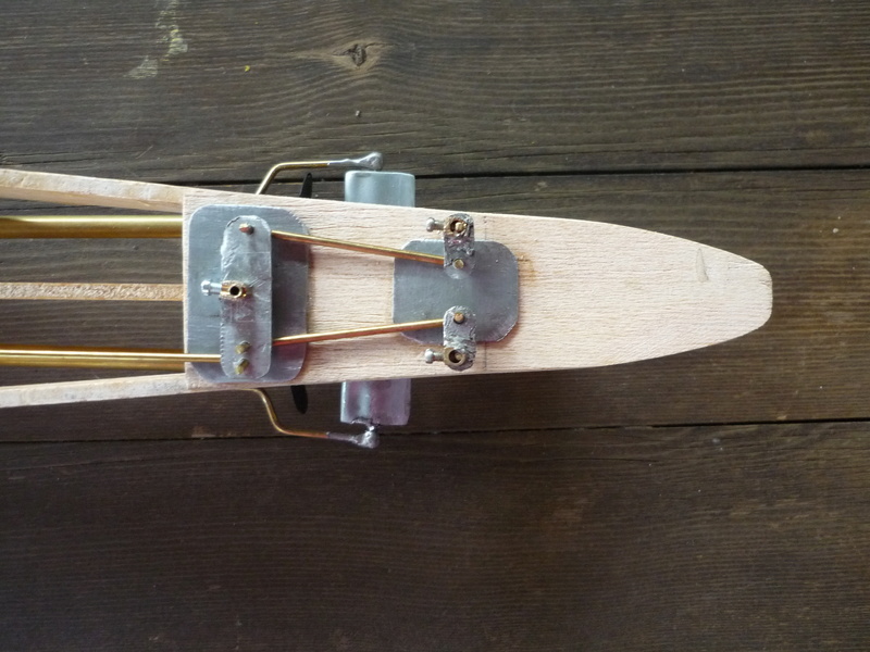
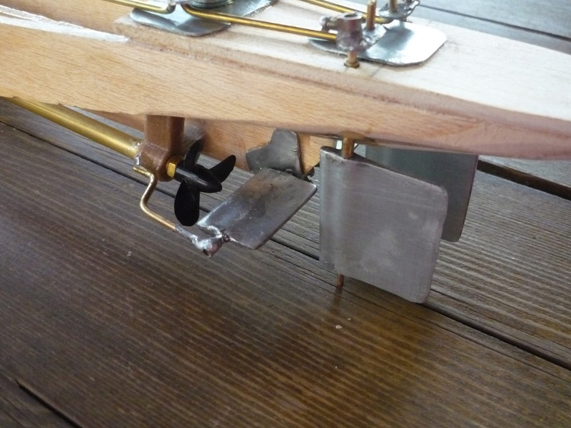
Dive planes and rudders were made out of a zinc sheet, bent and soldered. Pushrods are 2mm brass rods, sealed with rubber bellows.
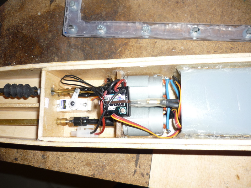
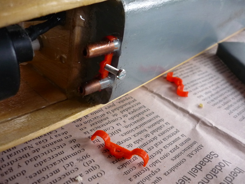
Motors used were taken from an old printer and fixed using a 3d printed piece. Another 3d printed piece is used to hold the propeller shafts. Everithing is glued in place with 30 min epoxy.
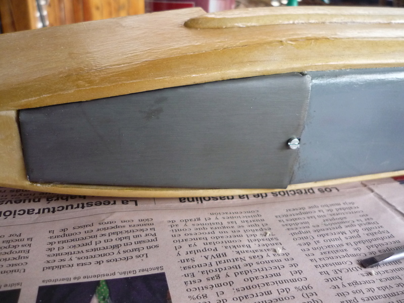
Next comes the big mistake of this submarine: The ballast tank: (Quite a strange shape!)
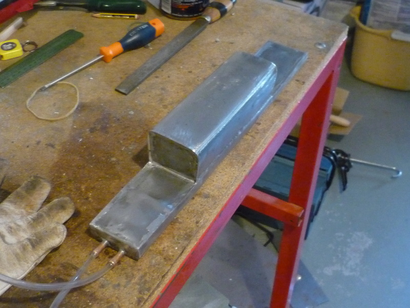
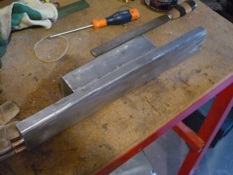
The model you can see on the background of the last photo is a static model I took as a reference.
Made out of 1 mm iron sheet, bent and soldered into shape, and then painted from the outside and from the inside filling it with paint and then removing it to prevent corrosion; It proved too long for the task, its never filled completely and water moves very fast inside it with nothing preventing that, making the submarine incontrollable when submerged. (More on that later, posible solutions, etc) Total volume of the tank is nearly 750 ml.
As a surface boat, performs well, but at the moment controlled diving is nearly imposible.
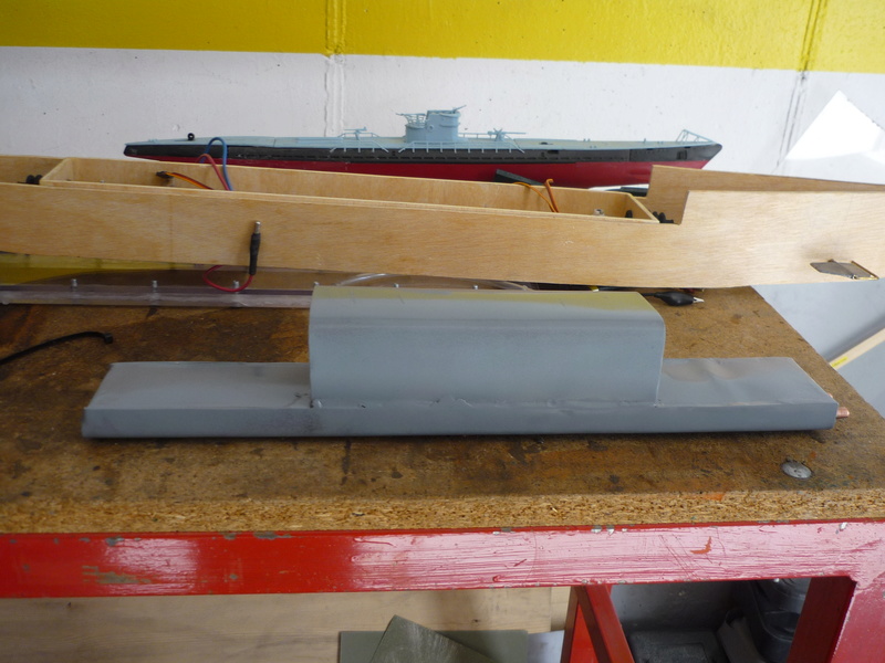
Unaware of the problems it will cause, the ballast tank was fixed to the hull with lots of silicone:
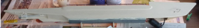
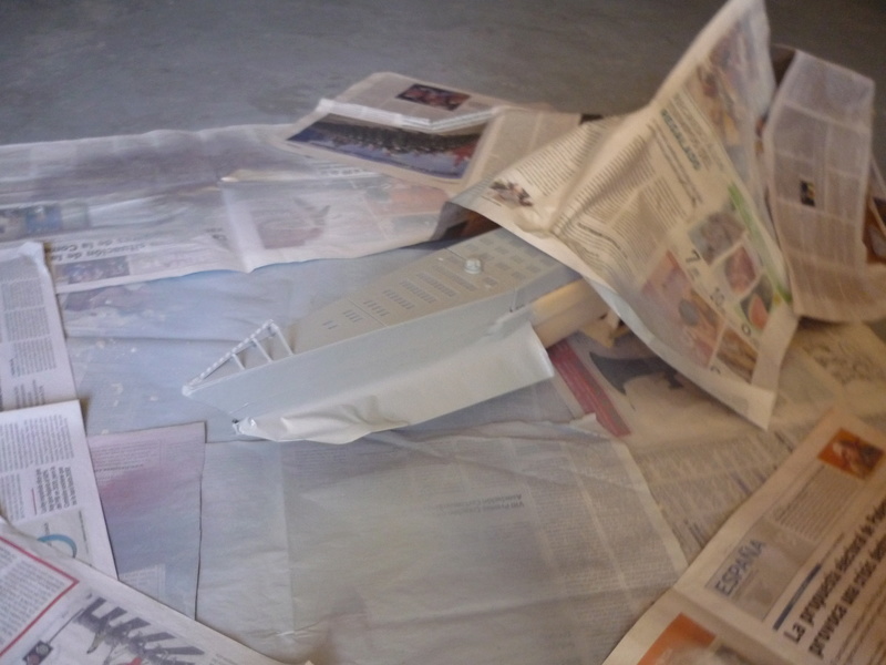
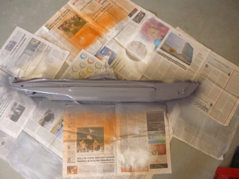
The hull was nearly completed and painted with a primer:
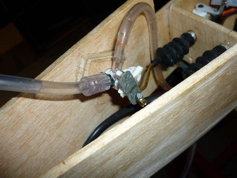
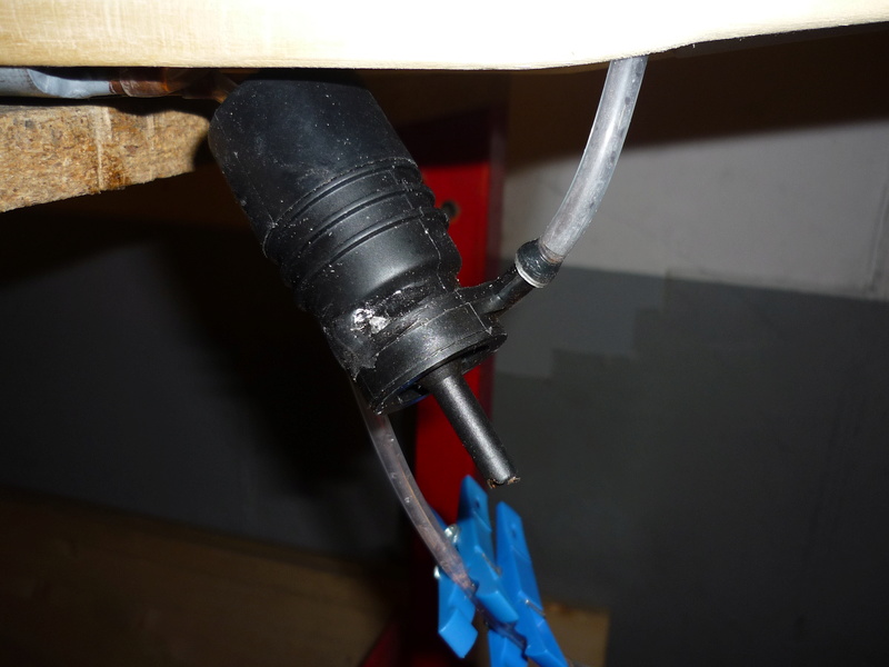
Ballast system: Windscreen water pump, servo operated three way valve,
Then the policarbonate sheet was cut to shape, drilled, fitted with screws and glued to the wtc:
The gasket was made out of soft silicone after trying numerous materials.
Then, two wood stripes were glued onto the sides of the sub.
All the wood parts were coated with epoxy paint:
Then, the deck, sail, guns etc. were designed in FreeCAD:
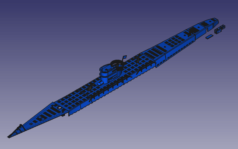
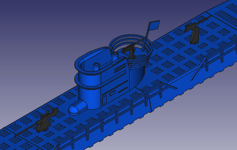
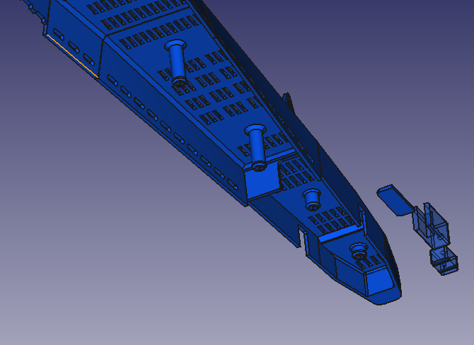
And then 3d printed using white abs, glued with acetone and fitted to the hull:
That black thing on the photo is the fuse cover. The fuse is used to switch on an off the entire submarine.
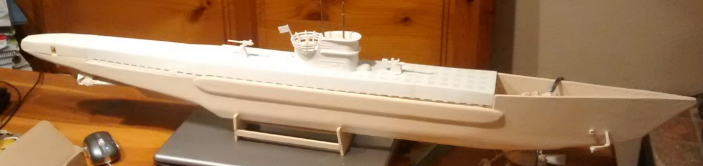
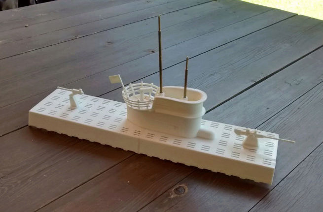
After all comes the painting job :
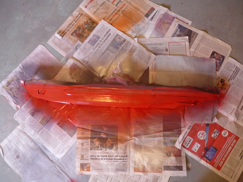
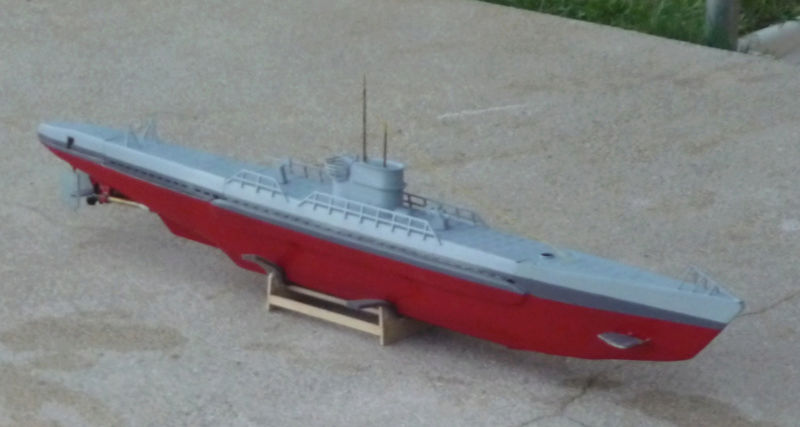
And the final result:
First trials in the swiming pool:
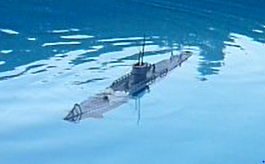
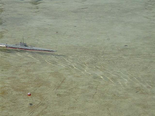
And in the local pond:
Result:
> Speed: A bit faster than scale.
> Turning: Fine. Small turning circle. Rudders work great.
> Diving: It dives, but it can't return to surface. After filling the tank, it goes vertical and any try to emerge causes compresed air to release and sinking the sub to the botom.
> Foward dive planes : Useless, even at 45 degrees seem to have no effect.
> Watertightness: Not leaked a single drop.
> Batteries: One 1300 mA 11.1 v lithium battery lasts about 45 mins-1 h
Ballast system explanation & posible solution:
> Here is the schematic of the ballast system: A "water sealed tank" or a "high presure pump" system:
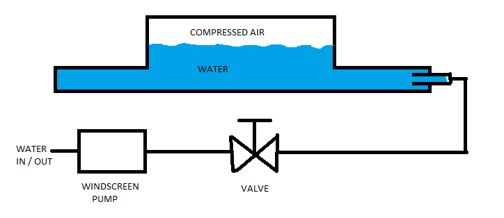
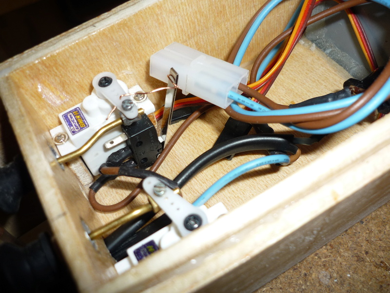
To dive, a servo opens the valve and presses a microswitch that activates a windscreeen pump, wich pushes water into the tank, compresing the air inside. Then , the valve is closed.
To emerge, simply open the valve and air presure will force the water out.
There comes the problems I have encountered:
1st: In a long tank, water moves back and foward very quickly, making the sub very inestable.
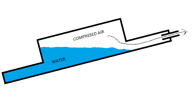
2nd: In certain situations, air can escape when openning the valve, loosing poresure and beeing unable to surface again.
Case A: Center of gravity (CG) foward, imposible to dive in a controlled manner, but able to surface.
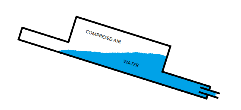
Case B: CG back, imposible to dive in a controlled manner, unable to surface, if the valve is opened, compresed air will escape before water. You have to get wet.
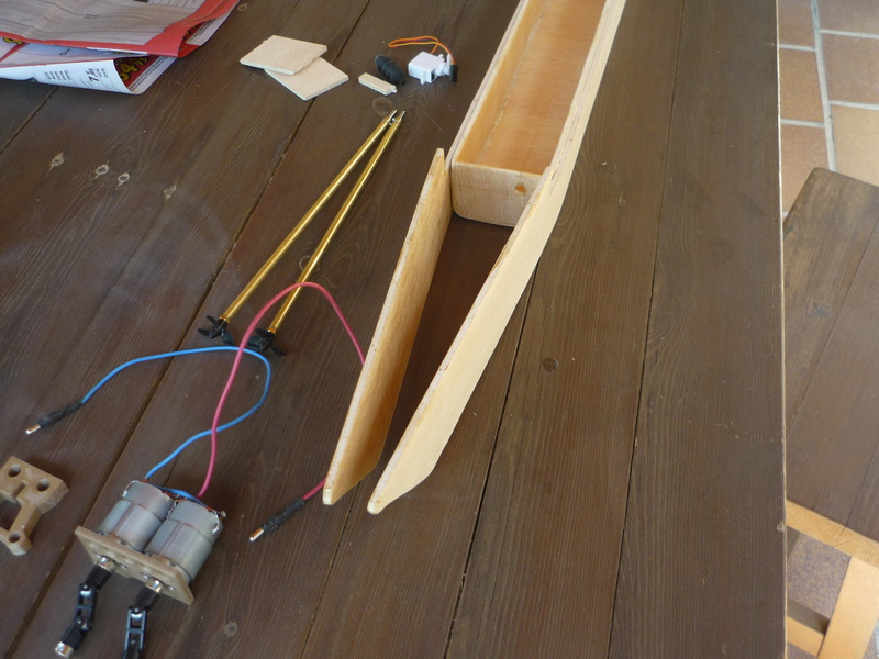
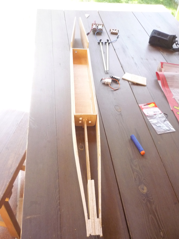
Posible solution:
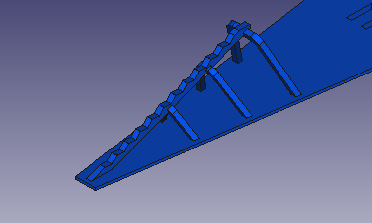
As I do not need all the volume of the tank, sides of it can be sacrificed to shorten it, thus making it more stable.
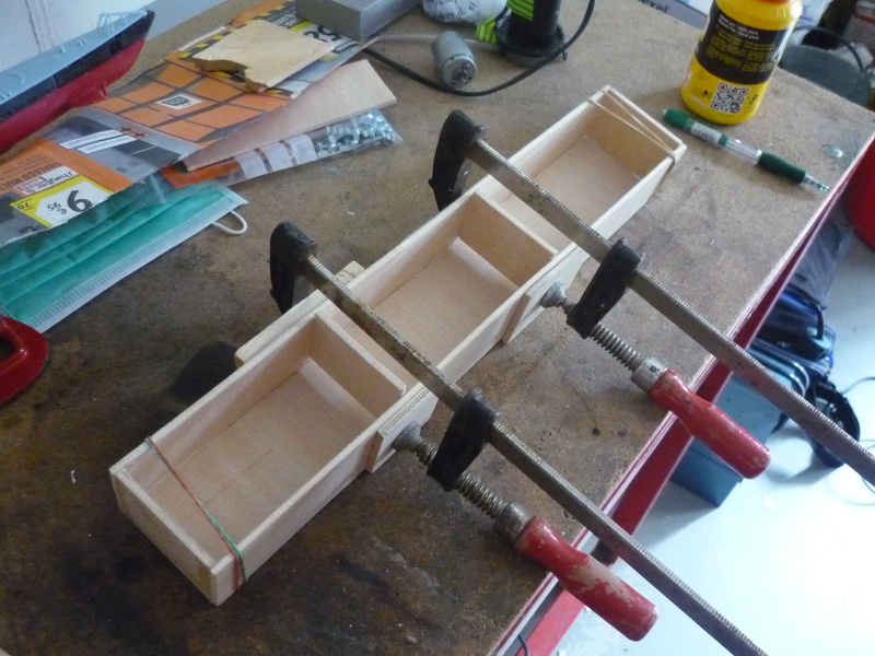
Furthermore, adding a kind of bulkheads inside will unable air to scape in any position (not turning the sub over) and willl certainly make the sub far more stable.
See the images:

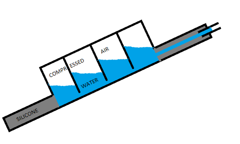
Now, how to put those bulkheads inside a 1 mm wall stell tank? The tank itself is the botom of the sub, s you can see in the photos, so the only way to do it is to cut it open, add the bulkheads, fill sides with silicone and close it again !
Comments
Post a Comment