
FlatCAM 8.994 Beta Tips


I'll be adding here some tips and how-tos on how on FlatCAM 8.994, an Open-Source PCB CAM tool.

This is a work in progress and it's mostly for my own reference. I'll be updating it as I discover new stuff. Note that procedures shown may not be correct or the most efficient. This is provided "as is".

FlatCAM's website: http://flatcam.org/

Installation: https://bitbucket.org/jpcgt/flatcam/downloads/

Create and save new project:

Load Gerbers & Excellon:

Single-sided isolation routing:

On the left pane, double-click your front copper gerber, and you'll be taken to a Properties window. Choose Isolation routing. If the left pane somehow disappears, you may go to View > Toggle project/Properties/Tool.


On tools & tools library:

From within the isolation window, delete default tools and choose the tool you want to use, or create a new one. See the screenshow on how to do so.
Here is how to configure a traditional V bit.


To be continued... Soon (TM) Don't you find it annoying when you are faced with this words, only to see the post is three years old? :)


Example PCBs

LED flasher schematic

Working demonstration

Rev. A PCB

0.5 & 0.8 mm traces (20 & 30 mil). Isolation routing, 0.1 mm depth, single pass. A pain to solder.
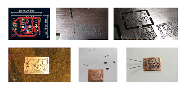
Rev. B PCB

0.3 & 0.5 mm traces (20 & 10 mil). Isolation routing, 0.1 mm depth, single pass (approx 2-3 min). Copper clear (approx 15 min). Easy to solder. Cleaning traces with an abrasive sponge is a bad idea with this thin traces...
Bottom left: Guess which one was done before and which one after tightening the screws on my CNC machine.


Comments

Popular posts from this blog

Split-ring compound epicyclic/planetary gearboxes

A while ago, I came across this strange thing called ‘split-ring compound epicyclic/planetary gearboxes’. They seemed really nice, extremely high gear ratios in compact, stackable modules. But the already existing models were not enough. I wanted to be able to design my own, and due to the lack of information on the subject, I had to do a little research and some math. Here is most of what I would have liked to find on the first place: 1. What is a planetary gearbox? Planetary gearboxes, as their name says, resemble planets orbiting around a “sun”. They are composed of a sun gear, in the center, two or more planet gears around it -and often fitted to a carrier- and a ring/annulus gear on the outside. As an image is worth a thousand words: Source Their main feature is a high reduction ratio in a small, flat space, and also, it is easy to couple the output of one gearbox to the input of another one, getting a two or more stage gearbox with such a high reduction ratio. But where is the i

Arduino Based Electronic Load

I have had some problems with my "lab power supply" and I wanted to build another one, so I thought a DC load may be handy to have around. The design is based around Dave Jone's design shown in this video , but with a couple more features, including:     -Arduino controlled.     -Voltage, current, power and temperature monitoring.     -CC and external in hardware modes and CP, Cr software modes.     -Over temperature, over power and over current protection (software) It can handle around 4 amps and 24 volts, limited by the mosfet. It's divided in two main boards. * UI Board: houses the 7 segment displays (I know one is bigger that the others, just what I had aroud...) and the keyboard. The display is multiplexed using a shift register. In addition, the four buttons are read taking advantage of the transistors switching the comon anodes, requiring only one additional pin. Only the first digit had decimal point, so one led was added for the second dig

Linear lab power supply

This is a dual channel linear lab power supply I have spent recent months building, much thanks to the help received in  this EEVBlog thread . All design files are available in this  GitHub repository . I will attempt to go over the general progress of the project, but please refer to the said thread for more information. Design requirements: Dual isolated channels. Adjustable voltage and current  30 V , 500 mA per channel. Digital voltage and current displays. Build stages: First, the case was made out of a wooden board and 3d printed front and back panels. Heatsinks were taken from old computers. One side of a 2x 10Vac and a 15 Vac transformer power each channel, plus a 12 Vac smaller transformer for the displays, fan and microcontroller. Ac voltages are rectified and filtered on a separate board. Here are some photos of the early development, initial circuit was based on the one found  here . Then came perfboard prototypes, testing and throubleshooting: