Sometimes a water alarm may come in handy around the house, to notify you of leaks so you can do something about it before the mess grows beyond control.
I designed and manufactured a rudimentary alarm that senses water through a simple conductive probe, and compains about it.
It made for a perfect excuse to get back up to speed with KiCad and LTSpice, to recover from MicroSIM (1996 edition, ever heard of it? me neither) which they make us use at school. Beeing able to pan and zoom using the mouse is definitely something I've missed.
Here is the schematic: A couple of transistors form an SCR-like circuit that latches on if water is detected. This powers a two transistor oscillator than in turn drives the buzzer. Almost zero power consumption on standby.
Most values are non-critical, and timings are difficult to predict in this kind of circuits, as transistors have to be driven with certain base current to turn the buzzer on and this interferes with the time constants of the RC sections that determine oscilation period. So final values for C3 and C4 were chosen experimentally.
One thing to note though, as this circuit is powered from 9 V and transistor bases are momentarily driven to -VCC, BE breakdown (about 6 V) has to be taken into account, as it can damage the transistors. Diodes D3 and D4 limit V_BE to -0.6 V. I haven't seen this in similar circuits, even powered from 12 V.
Note from the future: I ended up removing D1 so it only goes off when the "probe" is wet. This prevents the nice positive-feedback switching, but still works. I also changed R2 for a potentiometer so the "threshold" can be adjusted. Sometimes the residual water in the probe is enough to trigger the thing, even separating the wires a couple cm.
A better implementation would be as follows: Same circuit as before, on a hair trigger, but instead of switching the buzzer directly, it turns on a comparator circuit that can more acurately determine the presence of water. You could even make it shut up on its own after, say, 10 or 20 s. Or at this stage you could throw in a microcontroller...
Here is a screenshot of an LTSpice simulation to verify part of the design:
PCB layout in KiCad, using wide tracks for easier manufacturing:
And the 3D view: (The keen-eyed will notice this is a different version)
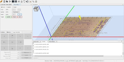
I used FlatCAM to generate the G-Code for my CNC mill. It's nice and all, yet online documentation seems to be out of date with the actual program one can download online, and for the life of me I cannot find a way to do internal board cuttouts (i.e a wide slot or similar). So for the slot near the battery and mounting holes I just drew toolpaths manually in FlatCAM.
For sending G-Code I use UGS. I like its simple interface, though it has its quirks. In order to use the auto-leveling function (surface probing) one has to do a search "G01 F" replace with "F" on the G-Code. Aside from this it works fine. I had to add a capacitor in parallel with the contact probe so as to eliminate some glitches. Now it works well.
Isolation routing:
I used two passes with depth around 0.2 mm with a 30º 0.2 mm engraving bit. One pass down 0.1 mm seems more than adequate. I've found feeding around 250 mm/min works for my purposes.
Drilling:
I drilled all holes with a 1 mm drill, though components with thin leads certainly do benefit from 0.8 mm holes when soldering, which I'll do next time.
Routing:
A 1.7 mm PCB endmill makes quick work of cutting the board out.
Finished board:
All components fitted:
An old 9V battery finds its contacts repurposed as a battery clip.
This is the underside of the board. Note the obligatory bodge wires as someone messed up during schematic entry.


Comments
Post a Comment